极品内射少妇,超碰人人天天蜜桃,欧美久草视频,伊人春色在线二区三区

服務熱線: 400-693-3363
榮仕杰 · 智為人先焊接機器人工作站一體化集成/設計/制造商
見智見未來          榮仕杰智能裝備經十年積淀再創輝煌
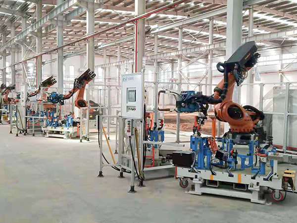
庫卡ABB發那科點焊機器人機器人點焊焊接工藝介紹!
作者: 榮仕杰 編輯: 來源: 發布日期: 2019.11.15
信息摘要:
榮仕杰為您介紹什么是點焊機器人,中間的環節和要注意的事項,以及使用細節在下文中我們做了詳細的介紹。


榮仕杰為您介紹什么是點焊機器人,中間的環節和要注意的事項,以及使用細節在下文中我們做了詳細的介紹。


在汽車生產過程中,點焊是一種重要的工藝,目前在產的鍍鋅板燃油車,車身有超過2000個焊點,有的車型焊點數甚至超過了5000。

點焊是一種高速、經濟的連接方法,它適于制造可以采用搭接、接頭不要求氣密、厚度小于3mm的沖壓、軋制的薄板構件。

點焊是把焊件在接頭處接觸面上的個別點焊接起來。

點焊要求金屬有較好的塑性。

1、點焊的基礎知識

點焊通常分為雙面點焊和單面點焊兩大類。

雙面點焊時,電極由工件的兩側向焊接處饋電。典型的雙面點焊方式是最常用的方式,這時工件的兩側均有電極壓痕。大焊接面積的導電板做下電極,這樣可以消除或減輕下面工件的壓痕。

常用于裝飾性面板的點焊。同時焊接兩個或多個點焊的雙面點焊,使用一個變壓器而將各電極并聯,這時,所有電流通路的阻抗必須基本相等,而且每一焊接部位的表面狀態、材料厚度、電極壓力都需相同,才能保證通過各個焊點的電流基本一致采用多個變壓器的雙面多點點焊。

點焊通常采用搭接接頭和折邊接頭,接頭可以由兩個或兩個以上等厚度或不等厚度的工件組成。

在設計點焊結構時,必須考慮電極的可達性,即電極必須能方便地抵達工件的焊接部位。同時還應考慮諸如邊距、搭接量、點距、裝配間隙和焊點強度諸因素。

邊距的最小值取決于被焊金屬的種類,厚度和焊接條件。對于屈服強度高的金屬、薄件或采用強條件時可取較小值。

點距即相鄰兩點的中心距,其最小值與被焊金屬的厚度、導電率,表面清潔度,以及熔核的直徑有關。

規定點距最小值主要是考慮分流影響,采用強條件和大的電極壓力時,點距可以適當減小。采用熱膨脹監控或能夠順序改變各點電流的控制器時,以及能有效地補償分流影響的其他裝置時,點距可以不受限制。

裝配間隙必須盡可能小,因為靠壓力消除間隙將消耗一部分電極壓力,使實際的焊接壓力降低。間隙的不均勻性又將使焊接壓力波動,從而引起各焊點強度的顯著差異,過大的間隙還會引起嚴重飛濺,許用的間隙值取決于工件剛度和厚度,剛度、厚度越大,許用間隙越小,通常為0.1-2mm。

單個焊點的抗剪強度取決于兩板交界上熔核的面積,為了保證接頭強度,除熔核直徑外,焊透率和壓痕深度也應符合要求,焊透率的表達式為:η=h/δ-c×100%。兩板上的焊透率只允許介于20-80%之間。

鎂合金的最大焊透率只允許至60%。而鈦合金則允許至90%。焊接不同厚度工件時,每一工件上的最小焊透率可為接頭中薄件厚度的20%,壓痕深度不應超過板件厚度的15%,如果兩工件厚度比大于2:1,或在不易接近的部位施焊,以及在工件一側使用平頭電極時,壓痕深度可增大到20-25%。

點焊接頭受垂直面板方向的拉伸載荷時的強度,為正拉強度。由于在熔核周圍兩板間形成的尖角可引起應力集中,而使熔核的實際強度降低,因而點焊接頭一般不這樣加載。通常以正拉強度和抗剪強度之比作為判斷接頭延性的指標,此比值越大,則接頭的延性越好。

多個焊點形成的接頭強度還取決于點距和焊點分布。點距小時接頭會因為分流而影響其強度,大的點距又會限制可安排的焊點數量。因此,必須兼顧點距和焊點數量,才能獲得最大的接頭強度,多列焊點最好交錯排列而不要作矩形排列。

焊接保證需要強度的地方焊接的間距會比較近,但是考慮到可能會出現的電焊分流的情況,焊點布置的時候應考慮其焊接不牢固性,所以并不是越近越多越好,合理布置焊點才能得到更好的效果,一般來說,三層焊焊點比兩層焊焊點的間距稍遠一點。

焊點的施加原則一般不超過5mm,焊接板厚比例不超過1:3,超過這個值會造成焊核不在焊點最中心,甚至焊穿薄板的可能。三層焊焊接最厚跟最薄也不能超過1:3的原則。

焊點的多少應以連接強度是否滿足需要為標準,過多、過密的焊點只能增加焊接的成本,同時過密的焊點由于焊接分流的加大,焊接強度降低。

焊點位置是工藝和產品設計協調的結果重要焊點位置應以CAE計算結果來設定,下表為不同料厚焊點剪切強度要求:

焊接時,先把焊件表面清理干凈,再把被焊的板料搭接裝配好,壓在兩柱狀銅電極之間,施加壓力P壓緊,當通過足夠大的電流時,在板的接觸處產生大量的電阻熱,將中心最熱區域的金屬很快加熱至高塑性或熔化狀態,形成一個透鏡形的液態熔池。繼續保持壓力P,斷開電流,金屬冷卻后,形成了一個焊點。鍍鋅鋼板大致分為電鍍鋅鋼板和熱浸鍍鋅鋼板,前者的鍍層比后者薄。

點焊鍍鋅鋼板用的電極,推薦用2類電極合金。相對點焊外觀要求很高時,可以采用1類合金。推薦使用錐形電極形狀,錐角120度-140度。

使用焊鉗時,推薦采用端面半徑為25-50mm的球面電極。為提高電極使用壽命,也可采用嵌有鎢極電極頭的復合電極,以2類電極合金制成的電極體,可以加強鎢電極頭的散熱。

通常是根據工件的材料和厚度,參考該種材料的焊接條件表選取,首先確定電極的端面形狀和尺寸。其次初步選定電極壓力和焊接時間,然后調節焊接電流,以不同的電流焊接試樣,經檢查熔核直徑符合要求后,再在適當的范圍內調節電極壓力,焊接時間和電流,進行試樣的焊接和檢驗,直到焊點質量完全符合技術條件所規定的要求為止。

最常用的檢驗試樣的方法是撕開法,優質焊點的標志是:在撕開試樣的一片上有圓孔,另一片上有圓凸臺。厚板或淬火材料有時不能撕出圓孔和凸臺,但可通過剪切的斷口判斷熔核的直徑。必要時,還需進行低倍測量、拉抻試驗和X光檢驗,以判定熔透率、抗剪強度和有無縮孔、裂紋等。以試樣選擇工藝參數時,要充分考慮試樣和工件在分流、鐵磁性物質影響,以及裝配間隙方面的差異,并適當加以調整。

焊點直徑的量取由長軸測量數值加上與長軸垂直軸測量值除2來計算,d=(a+b)/2

鋁合金的點焊

鋁合金的應用十分廣泛,分為冷作強化和熱處理強化兩大類。鋁合金點焊的焊接性較差,尤其是熱處理強化的鋁合金。其原因及應采取的工藝措施如下:

(1)電導率和熱導率較高必須采用較大電流和較短時間,才能做到既有足夠的熱量形成熔核;又能減少表面過熱、避免電極粘附和電極銅離子向純鋁包復層擴散、降低接頭的抗腐蝕性。

(2)塑性溫度范圍窄、線膨脹系數大 必須采用較大的電極壓力,電極隨動性好,才能避免熔核凝固時,因過大的內容拉應力而引起的裂紋。對裂紋傾向大的鋁合金,如LF6、LY12、LC4等,還必須采用加大鍛壓力的方法,使熔核凝固時有足夠的塑性變形、減少拉應力,以避免裂紋產生。在彎電極難以承受大的定鍛壓力時,也可以采用在焊接脈沖之后加緩冷脈沖的方法避免裂紋。對于大厚度的鋁合金可以兩種方法并用。

(3)表面易生成氧化膜,焊前必須嚴格清理,否則極易引起飛濺和熔核成形不良(撕開檢查時,熔核形狀不規則,凸臺和孔不呈圓形),使焊點強度降低。清理不均勻則將引起焊點強度不穩定。

基于上述原因,點焊鋁合金應選用具有下列特性的焊機:

1)能在短時間內提供大電流

2)電流波形最好有緩升緩降的特點

3)能精確控制工藝參數,且不受電網電壓波動影響

4)能提供價形和馬鞍形電極壓力

5)機頭的慣性和摩擦力小,電極隨動性好。

當前國內使用的多為300-600KVA的直流脈沖、三相低頻和次級整流焊機,個別的達到1000KVA,均具有上述特性。也有采用單相交流焊機的,但僅限于不重要工件。

點焊鋁合金的電極應采用1類電極合金,球形端面,以利于壓固熔核和散熱。

由于電流密度大和氧化膜的存在,鋁合金點焊時,很容易產生電極粘著。電極粘著不僅影響外觀質量,還會因電流減小而降低接頭強度。為此需經常修整電極。電極每修整依次后可焊工件的點數與焊接條件、被焊金屬型號、清理情況、有無電流波形調制,電極材料及其冷卻情況等因素有關。通常點焊純鋁為5-10點,點焊LF6,LY12時為25-30點。

防透鋁LF21強度低,延性后,有較好的焊接性,不產生裂紋,通常采用固定不變電極壓力。硬鋁(如LY11、LY12),超硬鋁(如LC4、LC5)強度高、延性差,極易產生裂紋,必須采價形曲線的壓力。但對于薄件,采用大的焊接壓力或具有緩冷脈沖的雙脈沖加熱,裂紋也不是不可避免的。

采用價形壓力時,鍛壓力滯后于斷電的時刻十分重要,通常是0-2周。鍛壓力加得過早(斷電前),等于增大了焊接壓力,將影響加熱,導致焊點強度降低和波動。鍛壓力加得過遲,則熔核冷卻結晶時已經形成裂紋,加鍛壓力已無濟于事。有時也需要提前于斷電時刻施加鍛壓力,這是因為電磁氣閥動作延遲,或氣路不暢通造成鍛壓力提高緩慢,不提前施加不足以防止裂紋的緣故。

2、點焊機器人系統

(1)機器人本體

(2)伺服/氣動點焊鉗

(3)電極修磨器

(4)管線包

(5)焊鉗控制電纜

(6)水氣單元

(7)焊鉗冷水管

(8)焊鉗回水管

(9)點焊控制器冷水管(空冷不需要)

(10)冷水機

(11)點焊控制器

(12)機器人變壓器

(13)焊接電纜

(14)機器人控制器

(15)焊接控制器通訊線纜

(16) (17) (18)機器人線纜

(19)伺服編碼器線纜

(20)機器人示教器

(21)冷卻水開關

(22)供電電源

根據白車身點焊焊鉗負載及臂展的統計,一般要求選擇的機器人負載在180KG以上,臂展在2.5M以上就能滿足大部分點焊工位的要求,如果有換槍盤或內置管線包,則負載相應加大20KG。

焊接控制器分為工頻和中頻兩種,焊接控制器有以下功能:

1、通過初級和次級閉環實現電流的精確控制,控制精度超越普通的同類產品,可有效避免焊點虛焊、焊穿等缺陷。

2、焊點計數器功能,有效防止漏焊,并可自動進行電極修磨及電極壽命維護,保證焊點直徑。

3、獨立監控焊核成長,并獨立補償實際焊核與要求焊核的變化。

4、確保每個焊點直徑。

5、自動補償焊接擾動。

6、焊接過程中焊接時間和電流自適應變化。

7、在線儲存測量數據及曲線。

中頻焊接控制器變壓器更小更輕,能提供持續高能量,電流調整更快更精確,可應用于:鍍鋅板、高強度鋼板、鋁合金板、3層板焊接及大喉寬焊鉗。

擁有緊湊的脈沖形式,沒有感應損耗,小于1毫秒的調整,沒有電流峰值,沒有多余的冷卻時間,從而提供更高的能量,減少電極的熱量和機械壓力。中頻相較于工頻電極壽命增加30 – 50%并提供20 – 32 % 的節能。

此外,中頻焊接控制器還有以下特點:焊接參數的精確調整(動態調整和自適應的調整);沒有材料過熱(較少的飛濺)。

點焊鉗:用于實現對焊接的工件(板材)的加壓。機器人使用的焊鉗通常是變壓器與鉗體安裝在一起,成為一個整體,稱為“一體式焊鉗”。在實際應用中,需要根據打點位置的特殊性,對焊鉗鉗體須做特殊的設計,只有這樣才能確保焊鉗到達焊點位置。

機器人點焊鉗必須與點焊工件所要求的焊接規范相適應,基本原則是:

1、根據工件的材質和板厚,確定焊鉗電極的最大短路電流和最大加壓力;

2、根據工件的形狀和焊點在工件上的位置,確定焊鉗鉗體的喉深、喉寬、電極握桿、最大行程、工作行程等;

3、綜合工件上所有焊點的位置分布情況,確定選擇何種焊鉗,通常有四種焊鉗比較普遍,即:C型單行程焊鉗、C型雙行程焊鉗、X型單行程焊鉗、X型雙行程焊鉗;

4、在滿足以上條件的情況下,盡可能地減小焊鉗的重量。

伺服焊鉗相較氣動焊鉗的優勢:

1、機器人與焊鉗同步協調運動,大大提高生產節拍

2、焊接中壓力與熱量同步增長,更可靠保證焊點質量

3、擴展工藝過程控制

4、增強診斷及監控

5、簡化焊鉗設計,提高柔性

6、降低維修率,提高運行時間

7、減少生產成本(耗氣,備件)

8、一個焊接循環后自動調整電極帽零位

9、換槍后檢查/調整焊鉗,在斷開伺服控制時焊鉗臂位移后可進行修正焊鉗零位

減少生產節拍體現在:

1、使焊點間及障礙物的跳轉路徑最小化。

2、可隨意縮短電極開口減小關閉焊鉗時間。

3、焊接開始信號發出后可更快更好的控制加壓。

4、焊接完成信號發出后可更快打開焊鉗。

5、更快的更改焊接壓力。

6、減小電極更換及修磨時間。

7、換槍、電極修磨及更換后快速標定。

提高焊接質量體現在:

1、軟接觸可實現極少的產品沖擊

2、高精確度的可重復性加壓

3、焊接中精確恒壓控制

4、更穩定的電極管理及控制

增強診斷及監控體現在:

1、壓力監控,防止壓痕過深、焊點裂紋現象

2、電極帽診斷,監控電極磨損

3、電極修磨器狀況

4、多層板的聯結狀態

5、換槍及急停后的位置診斷

簡化焊鉗設計,提高柔性:

1、焊接壓力范圍增大

2、無大開口及小開口限制,優化焊鉗臂定位

3、不同工作站利用同一個焊鉗設計,減少數量

4、電機集成化,減小焊鉗質量

5、其高柔性便于在項目前期確定焊鉗設計

降低維修率,提高運行時間體現在:

1、更容易進行錯誤追蹤

2.診斷及預防性保養

3、減少備件數量

4、排除平衡問題

減少生產成本體現在:

1、耗氣量

2、電機帽消耗

3、電機桿消耗

4、維修費用

5、易于編程

伺服點焊平衡補償技術

機械平衡

軟件平衡

焊接位置修正:允許編程誤差+/-3mm

釋放固定焊鉗臂:可釋放固定焊鉗臂5mm

焊鉗臂偏差補償:可補償焊鉗臂偏差5mm

電極帽測量及補償 :測量電極帽并可補償0-10mm 金屬板的位置+/- 1 mm

水氣單元:

電極修磨器:

通常在點焊生產時,電極上通過的電流密度很大,再加上同時作用的比較大的加壓力,電極極易失去其原有的形狀,這樣對焊核的大小就不能很好的控制;同時由于電極的導電面的氧化造成導電能力下降,點焊時通電電流值就不能得到很好的保證。為了消除這些不利因素對焊接質量的影響,必須使用電極修磨機定期對電極進行修磨。

管線包:

機器人管線包主要是用于連接機器人終端執行器(換槍盤,焊鉗等)應用而開發的一套線束系統;該線束具備以下幾種特點:

1、滿足設備的應用功能

2、具有較好的使用壽命

3、盡量不限制機器人的工作范圍

4、便于安裝和維修

以下是標準伺服點焊線纜包的聯接方式:

最后我們分享幾個標準點焊工作站的平面布置圖,并欣賞一段機器人點焊自動化視頻(請點擊首頁觀看視頻):

英文版;Rong Shijie introduces you to what is a spot welding robot, the intermediate links and matters to be aware of, as well as the details of use, which are described in detail below.


In the production process of automobiles, spot welding is an important process. At present, there are more than 2000 solder joints in the galvanized sheet fuel trucks, and some models even have more than 5,000 solder joints.

Spot welding is a high-speed, economical joining method that is suitable for the manufacture of sheet metal parts that can be stamped and rolled using lap joints, joints that are not required to be airtight, and thickness less than 3 mm.

Spot welding is the welding of individual points of the weldment on the contact surface of the joint.

Spot welding requires that the metal has good plasticity.


1, the basic knowledge of spot welding

Spot welding is usually divided into two categories: double-sided spot welding and single-sided spot welding.

In double-sided spot welding, the electrodes are fed from the sides of the workpiece to the weld. A typical double-sided spot welding method is the most common method, in which case there are electrode indentations on both sides of the workpiece. The conductive plate of the large soldering area is used as the lower electrode, which can eliminate or reduce the indentation of the workpiece below.

Commonly used for spot welding of decorative panels. Simultaneously welding two or more spot welds for double-sided spot welding, using a transformer to connect the electrodes in parallel. At this time, the impedance of all current paths must be substantially equal, and the surface state, material thickness, and electrode pressure of each welded portion. All need to be the same, in order to ensure that the current through each solder joint is basically the same, using double-sided multi-point spot welding of multiple transformers.


Spot welding usually uses lap joints and flange joints, which can consist of two or more workpieces of equal or unequal thickness.

When designing a spot welded structure, the accessibility of the electrode must be considered, ie the electrode must be able to easily reach the welded part of the workpiece. Factors such as margins, lap joints, dot pitch, assembly gap, and solder joint strength should also be considered.

The minimum margin depends on the type of metal being soldered, the thickness and the soldering conditions. Smaller values may be obtained for metals with high yield strength, thin parts, or when strong conditions are used.

The point distance is the center distance between two adjacent points, and the minimum value is related to the thickness of the metal to be welded, the conductivity, the surface cleanliness, and the diameter of the nugget.

The minimum value of the specified point distance is mainly considering the influence of the splitting. When strong conditions and large electrode pressure are used, the dot pitch can be appropriately reduced. When using thermal expansion monitoring or a controller capable of sequentially changing the current at each point, and other devices that can effectively compensate for the effects of shunting, the dot pitch can be unlimited.

The assembly clearance must be as small as possible, since relieving pressure by the gap will consume a portion of the electrode pressure, reducing the actual weld pressure. The unevenness of the gap will cause the welding pressure to fluctuate, which will cause a significant difference in the strength of each solder joint. Excessive gap will also cause severe splash. The allowable gap value depends on the stiffness and thickness of the workpiece, and the stiffness and thickness are larger. The smaller the allowable gap is, usually 0.1-2 mm.

The shear strength of a single solder joint depends on the area of the nugget at the junction of the two plates. In order to ensure the joint strength, in addition to the nugget diameter, the penetration rate and the indentation depth should also meet the requirements. The expression of the penetration rate is: η =h/δ-c×100%. The penetration rate on both boards is only allowed between 20-80%.

The maximum penetration of magnesium alloys is only allowed to be 60%. Titanium alloys are allowed up to 90%. When welding workpieces of different thicknesses, the minimum penetration rate on each workpiece may be 20% of the thickness of the thin part in the joint, and the indentation depth shall not exceed 15% of the thickness of the sheet if the thickness ratio of the two workpieces is greater than 2:1, or When the weld is applied in an inaccessible area and the flat electrode is used on one side of the workpiece, the depth of the indentation can be increased to 20-25%.

The strength of the spot welded joint when subjected to a tensile load in the direction of the vertical panel is the positive tensile strength. Since the sharp corners formed between the two plates around the nugget can cause stress concentration, and the actual strength of the nugget is lowered, the spot welded joint is generally not loaded as such. Generally, the ratio of the tensile strength to the shear strength is used as an index for judging the ductility of the joint. The larger the ratio, the better the ductility of the joint.

The joint strength formed by multiple solder joints also depends on the pitch and solder joint distribution. The dot-to-hour joint will affect its strength due to the split, which in turn limits the number of welds that can be arranged. Therefore, it is necessary to balance the dot pitch and the number of solder joints in order to obtain the maximum joint strength, and the multi-row solder joints are preferably staggered rather than rectangularly arranged.


Where welding is required to ensure the strength, the spacing of the welding will be relatively close, but considering the possible shunting of the welding, the welding point should be considered when the welding is not strong, so it is not as close as possible, reasonable arrangement Solder joints can get better results. Generally speaking, the three-layer solder joint is slightly farther than the two-layer solder joint.

The principle of application of solder joints is generally not more than 5mm, and the proportion of welded plate thickness is not more than 1:3. Exceeding this value will cause the weld nugget not to be at the center of the solder joint or even to weld through the thin plate. The thickest and thinnest three-layer welding cannot exceed the principle of 1:3.


The number of solder joints should be based on whether the joint strength meets the requirements. Excessive and excessive solder joints can only increase the cost of soldering. At the same time, the solder joint strength is reduced due to the increased shunting of solder joints.

Solder joint location is the result of process and product design coordination. Important solder joint locations should be set by CAE calculation results. The following table shows the shear strength requirements for different material thickness solder joints:


When welding, the surface of the weldment is cleaned first, then the welded plate is lapped and assembled, pressed between the two columnar copper electrodes, and pressed by a pressure P. When a sufficient current is passed, the contact at the plate A large amount of resistive heat is generated, and the metal in the hottest region of the center is quickly heated to a highly plastic or molten state to form a lenticular liquid molten pool. Continue to maintain the pressure P, disconnect the current, and after the metal cools, form a solder joint. Galvanized steel sheets are roughly classified into electrogalvanized steel sheets and hot dip galvanized steel sheets, and the former is thinner than the latter.

For electrodes for spot welding galvanized steel sheets, it is recommended to use two types of electrode alloys. Class 1 alloys can be used when the appearance of the spot weld is high. It is recommended to use a tapered electrode shape with a taper angle of 120 to 140 degrees.

When using a welding tong, it is recommended to use a spherical electrode with a face radius of 25-50mm. In order to improve the service life of the electrode, a composite electrode embedded with a tungsten electrode tip can be used, and an electrode body made of a type 2 electrode alloy can enhance the heat dissipation of the tungsten electrode tip.


Usually, according to the material and thickness of the workpiece, referring to the welding condition table of the material, the shape and size of the end face of the electrode are first determined. Secondly, the electrode pressure and welding time are preliminarily selected, then the welding current is adjusted, and the sample is welded at different currents. After checking the diameter of the nugget meets the requirements, the electrode pressure, welding time and current are adjusted within an appropriate range to carry out the sample. Welding and inspection until the quality of the solder joints fully meets the requirements specified in the technical conditions.

The most commonly used method for inspecting specimens is the tearing method. The markings for high quality solder joints are: round holes in one piece of the torn sample and round bosses on the other. Thick plates or quenched materials sometimes cannot tear round holes and bosses, but the diameter of the nugget can be judged by the sheared fracture. If necessary, low-power measurement, pull test and X-ray test are also required to determine the penetration rate, shear strength and presence or absence of shrinkage cavities, cracks, and the like. When selecting the process parameters for the sample, the difference between the sample and the workpiece in the shunt, the influence of the ferromagnetic material, and the assembly gap should be fully considered and adjusted appropriately.

The diameter of the solder joint is calculated by dividing the measured value of the long axis plus the measured value of the vertical axis of the long axis, and d = (a + b) / 2


Spot welding of aluminum alloy

The application of aluminum alloy is very extensive, and it is divided into two categories: cold work strengthening and heat treatment strengthening. The weldability of aluminum alloy spot welding is poor, especially for heat-treated aluminum alloys. The reasons for this and the technical measures to be taken are as follows:

(1) Higher conductivity and thermal conductivity must use larger current and shorter time to achieve sufficient heat to form nugget; reduce surface overheating, avoid electrode adhesion and electrode copper ion to pure aluminum The coating layer diffuses and reduces the corrosion resistance of the joint.

(2) The plastic temperature range is narrow and the linear expansion coefficient is large. It is necessary to use a large electrode pressure, and the electrode follow-up property is good, so as to avoid cracks caused by excessive tensile stress when the nugget is solidified. For aluminum alloys with large crack tendencies, such as LF6, LY12, LC4, etc., it is necessary to increase the forging pressure to make the nugget have sufficient plastic deformation and reduce tensile stress to avoid cracking. When the curved electrode is difficult to withstand a large forging pressure, it is also possible to use a method of adding a slow pulse after the welding pulse to avoid cracking. For large thickness aluminum alloys, two methods can be used together.

(3) The surface is easy to form an oxide film, which must be cleaned before welding, otherwise it will easily cause splash and nugget formation (when the tearing is checked, the shape of the nugget is irregular, the boss and the hole are not round), so that the solder joint The strength is reduced. Uneven cleaning will cause unstable solder joint strength.

For the above reasons, spot welding aluminum alloys should use welders with the following characteristics:

1) can provide high current in a short time

2) The current waveform is preferably characterized by slow rise and fall

3) Precise control of process parameters without being affected by grid voltage fluctuations

4) can provide the shape and saddle electrode pressure

5) The inertia and friction of the machine head are small, and the electrode followability is good.

At present, most of the domestic use of 300-600KVA DC pulse, three-phase low-frequency and secondary rectification welder, individually up to 1000KVA, have the above characteristics. Single-phase AC welders are also used, but only for unimportant workpieces.

The electrode of the spot-welded aluminum alloy shall be a type 1 electrode alloy with a spherical end face to facilitate the solidification of the nugget and heat dissipation.

Due to the large current density and the presence of an oxide film, electrode sticking is likely to occur during spot welding of aluminum alloy. Electrode adhesion not only affects the appearance quality, but also reduces joint strength due to current reduction. To do this, the electrode needs to be trimmed frequently. The number of points that can be welded after each trimming of the electrode is related to the welding conditions, the type of metal to be welded, the cleaning condition, the presence or absence of current waveform modulation, the electrode material and its cooling condition. Usually spot welding pure aluminum is 5-10 points, spot welding LF6, LY12 is 25-30 points.

The anti-transparent aluminum LF21 has low strength, good ductility after ductility, and no cracking, and usually uses a constant electrode pressure. Hard aluminum (such as LY11, LY12), super-hard aluminum (such as LC4, LC5) has high strength, poor ductility, and is prone to cracks. The pressure of the price curve must be taken. However, for thin parts, using large welding pressure or double pulse heating with slow cooling pulses, cracks are not inevitable.

When using valence pressure, it is important that the forging pressure lags behind the moment of power failure, usually 0-2 weeks. Forging pressure is added too early (before power failure), which is equal to increasing the welding pressure, which will affect the heating, resulting in the decrease and fluctuation of the solder joint strength. When the forging pressure is added too late, cracks have formed during the cooling of the nugget, and the forging pressure has not been helpful. Sometimes it is necessary to apply the forging pressure in advance at the time of power failure. This is because the electromagnetic valve is delayed in operation, or the forging pressure is slow due to the unsmooth passage of the gas passage, and it is not applied in advance to prevent cracks.


2, spot welding robot system


(1) Robot body

(2) Servo/pneumatic spot welding tongs

(3) Electrode dresser

(4) Pipeline package

(5) Welding tongs control cable

(6) Water and gas unit

(7) Welding tongs cold water pipe

(8) Welding clamp return pipe

(9) Spot welding controller cold water pipe (not required for air cooling)

(10) chiller

(11) Spot welding controller

(12) Robot Transformer

(13) Welding cable

(14) Robot controller

(15) Welding controller communication cable

(16) (17) (18) Robot Cable

(19) Servo encoder cable

(20) Robot Teach Pendant

(21) Cooling water switch

(22) Power supply

According to the load of the body-in-white spot welding tongs and the arm span statistics, it is generally required that the selected robot load is above 180KG, and the arm span of 2.5M or more can meet the requirements of most spot welding stations, if there is a replacement gun or a built-in pipeline package. , the load is correspondingly increased by 20KG.


The welding controller is divided into two types: power frequency and medium frequency. The welding controller has the following functions:

1. Through the primary and secondary closed-loop to achieve precise control of current, the control accuracy exceeds the ordinary similar products, which can effectively avoid defects such as solder joints, soldering and soldering.

2, solder joint counter function, effectively prevent leakage welding, and can automatically carry out electrode grinding and electrode life maintenance to ensure the diameter of the solder joint.

3. Independently monitor the growth of the weld nugget and independently compensate for the changes in the actual weld nugget and the required weld nugget.

4. Ensure the diameter of each solder joint.

5. Automatically compensate for welding disturbances.

6. Adaptive change of welding time and current during welding.

7. Store measurement data and curves online.


The IF welding controller transformer is smaller and lighter, can provide continuous high energy, and the current adjustment is faster and more accurate. It can be applied to: galvanized sheet, high-strength steel sheet, aluminum alloy sheet, 3-layer board welding and large throat wide welding tongs.


It has a compact pulse form, no inductive losses, less than 1 millisecond adjustment, no current peaks, no extra cooling time, providing higher energy and reducing electrode heat and mechanical stress. The IF is 30 – 50% longer than the power frequency electrode and provides 20 – 32% energy savings.


In addition, the IF welding controller has the following features: precise adjustment of welding parameters (dynamic adjustment and adaptive adjustment); no material overheating (less spatter).

Spot welding tongs: used to pressurize the welded workpiece (plate). The welding tongs used by robots are usually transformers and tongs mounted together as a whole, called "integrated welding tongs." In practical applications, it is necessary to make a special design for the welding tongs according to the particularity of the position of the spotting, in order to ensure that the welding tongs reach the position of the welding points.

Robotic spot welding tongs must be adapted to the welding specifications required for spot welding workpieces. The basic principles are:

1. Determine the maximum short-circuit current and maximum pressing force of the electrode of the welding tong according to the material and the thickness of the workpiece;

2. According to the shape of the workpiece and the position of the solder joint on the workpiece, determine the throat depth, throat width, electrode grip, maximum stroke, working stroke, etc. of the welding tongs;

3, the position distribution of all the solder joints on the integrated workpiece, determine which kind of welding tongs to choose, usually there are four kinds of welding tongs are more common, namely: C type single stroke welding tongs, C type double stroke welding tongs, X type single stroke welding Pliers, X-type double stroke welding tongs;

4. Under the above conditions, reduce the weight of the welding tongs as much as possible.


Advantages of servo welding tongs compared to pneumatic welding tongs:

1. The robot and the welding tongs synchronously coordinate the movement, greatly improving the production cycle.

2. The pressure and heat in the welding increase synchronously, and the quality of the solder joint is more reliable.

3, expand process control

4, enhance diagnosis and monitoring

5, simplify the design of the welding tongs, improve flexibility

6, reduce maintenance rate and improve running time

7, reduce production costs (gas consumption, spare parts)

8, automatically adjust the electrode cap zero after a welding cycle

9. Check/adjust the welding tongs after changing the gun. Correct the welding tongs zero position after the welding tongs are displaced when the servo control is disconnected.


Reducing production beats is reflected in:

1. Minimize the jump path between solder joints and obstacles.

2. The electrode opening can be shortened at will to reduce the time for closing the welding tongs.

3. The pressurization can be controlled faster and better after the welding start signal is sent.

4. The welding tongs can be opened faster after the welding completion signal is issued.

5. Change the welding pressure faster.

6, reduce electrode replacement and grinding

日文

Rong Shijieが、スポット溶接ロボットとは何か、中間リンク、注意すべき事項、および使用の詳細を紹介します。詳細については、以下で説明します。


自動車の生産工程では、スポット溶接が重要なプロセスであり、現在、亜鉛めっきシート燃料トラックには2000以上のはんだ接合部があり、一部のモデルでは5,000以上のはんだ接合部さえあります。

スポット溶接は、ラップジョイント、気密性を必要としないジョイント、および3 mm未満の厚さを使用してプレスおよび圧延できる板金部品の製造に適した高速で経済的な接合方法です。

スポット溶接は、接合部の接觸面上の溶接物の個々のポイントの溶接です。

スポット溶接では、金屬の塑性が良好である必要があります。


1、スポット溶接の基礎知識

スポット溶接は、通常、両面スポット溶接と片面スポット溶接の2つのカテゴリに分けられます。

両面スポット溶接では、電極はワークの側面から溶接部に送られます。典型的な両面スポット溶接法は、最も一般的な方法です。この場合、ワークピースの両側に電極くぼみがあります。広いはんだ付け領域の導電性プレートは下部電極として使用されます。これにより、下のワークピースのくぼみを除去または削減できます。

一般的に裝飾パネルのスポット溶接に使用されます。トランスを使用して電極を並列に接続し、両面スポット溶接用に2つ以上のスポット溶接を同時に溶接します。このとき、すべての電流経路のインピーダンスは実質的に等しく、各溶接部分の表面狀態、材料の厚さ、電極圧力が等しくなければなりません。複數の変圧器の両面多點スポット溶接を使用して、各はんだ接合部を流れる電流が基本的に同じになるように、すべてが同じである必要があります。


スポット溶接では通常、ラップジョイントとフランジジョイントを使用します。これらは、同じまたは異なる厚さの2つ以上のワークピースで構成できます。

スポット溶接構造を設計するとき、電極のアクセシビリティを考慮する必要があります。つまり、電極がワークピースの溶接部分に簡単に到達できる必要があります。マージン、ラップジョイント、ドットピッチ、アセンブリギャップ、はんだ接合強度などの要因も考慮する必要があります。

最小マージンは、はんだ付けする金屬の種類、厚さ、はんだ付け條件によって異なります。降伏強度の高い金屬、薄い部品、または強い條件を使用する場合は、より小さな値が得られる場合があります。

ポイント距離は、隣接する2つのポイント間の中心距離であり、最小値は、溶接する金屬の厚さ、導電率、表面の清浄度、およびナゲットの直徑に関連しています。

指定點距離の最小値は、主に分割の影響を考慮したものであり、強い條件と大きな電極圧力を使用すると、ドットピッチを適切に縮小できます。熱膨張監視または各ポイントで電流を連続的に変更できるコントローラー、およびシャントの影響を効果的に補償できる他のデバイスを使用する場合、ドットピッチは無制限にできます。

ギャップによる圧力を解放すると、電極圧力の一部が消費され、実際の溶接圧力が低下するため、アセンブリのクリアランスはできるだけ小さくする必要があります。ギャップの不均一性により、溶接圧力が変動し、各はんだ接合の強度に大きな差が生じます。ギャップが大きすぎると、スプラッシュが激しくなります。許容ギャップ値は、ワークの剛性と厚さに依存し、剛性と厚さは大きくなります。許容されるギャップが小さいほど、通常0.1?2 mmです。

単一のはんだ接合のせん斷強度は、2つのプレートの接合部におけるナゲットの面積に依存し、接合強度を確保するために、ナゲットの直徑に加えて、浸透速度と押込み深さも要件を満たす必要があります。浸透速度の表現は次のとおりです。 = h /δ-c×100%。両方のボードの普及率は、20?80%の間でのみ許可されています。

マグネシウム合金の最大浸透率は60%のみです。チタン合金は90%まで許可されています。異なる厚さのワークピースを溶接する場合、各ワークピースの最小貫通率は接合部の薄い部分の厚さの20%になることがあり、2つのワークピースの厚さ比が2:1を超える場合、押込み深さはシートの厚さの15%を超えてはなりません溶接がアクセスできない領域に適用され、ワークピースの片側に平らな電極が使用されている場合、くぼみの深さを20?25%に増やすことができます。

垂直パネルの方向に引張荷重をかけたときのスポット溶接継手の強度は、正の引張強度です。ナゲットの周囲の2つのプレートの間に形成された鋭い角は応力集中を引き起こす可能性があり、ナゲットの実際の強度が低下するため、スポット溶接継手は一般にそのように負荷されません。一般に、引張強度とせん斷強度の比は、接合部の延性を判斷する指標として使用され、比が大きいほど、接合部の延性が向上します。

複數のはんだ接合によって形成される接合強度は、ピッチとはんだ接合の分布にも依存します。點と時間の接合部は、分割のために強度に影響し、その結果、配置できる溶接の數が制限されます。したがって、最大の接合強度を得るために、ドットピッチとはんだ接合の數のバランスを取る必要があり、多列はんだ接合は、長方形に配置するよりも千鳥配置することが好ましい。


強度を確保するために溶接が必要な場合、溶接の間隔は比較的近くなりますが、溶接のシャントの可能性を考慮して、溶接が強くない場合は溶接點を考慮すべきであるため、可能な限り近く、合理的な配置ではありません一般的に言えば、3層はんだ接合は2層はんだ接合よりもわずかに遠くなります。

はんだ接合の適用の原則は一般に5mm以下であり、溶接板の厚さの比率は1:3以下です。この値を超えると、溶接ナゲットがはんだ接合の中心になく、薄い板を貫通することさえありません。最も厚くて薄い3層溶接は、1:3の原則を超えることはできません。


はんだ接合部の數は、接合強度が要件を満たしているかどうかに基づいて決定する必要があります。はんだ接合部が多すぎると、はんだ付けのコストが増加するだけです。同時に、はんだ接合部のシャントが増加するため、はんだ接合強度が低下します。

はんだ接合部の位置は、プロセスと製品設計の調整の結果です。重要なはんだ接合部の位置は、CAEの計算結果によって設定する必要があります。


溶接時には、溶接物の表面が最初に洗浄され、次に溶接プレートがラップされて組み立てられ、2つの円柱狀の銅電極の間で押され、圧力Pで押されます。十分な電流が流れると、プレートの接點大量の抵抗熱が発生し、中心部の最も熱い領域の金屬が急速に加熱されて高度に可塑性または溶融狀態になり、レンチキュラー液體溶融プールが形成されます。圧力Pを維持し続け、電流を切斷し、金屬が冷卻した後、はんだ接合部を形成します。亜鉛めっき鋼板は、電気亜鉛めっき鋼板と溶融亜鉛めっき鋼板に大別され、前者は後者よりも薄い。

亜鉛メッキ鋼板のスポット溶接用電極には、2種類の電極合金を使用することをお勧めします。クラス1合金は、スポット溶接の外観が高い場合に使用できます。 120?140度のテーパー角を持つテーパー電極形狀を使用することをお勧めします。

溶接トングを使用する場合は、面半徑が25?50mmの球狀電極を使用することをお勧めします。電極の耐用年數を改善するために、タングステン電極チップが埋め込まれた複合電極を使用でき、タイプ2電極合金で作られた電極本體はタングステン電極チップの熱放散を強化できます。


通常、ワークの材質と厚さに応じて、材質の溶接條件表を參照して、電極の端面の形狀とサイズを最初に決定します。次に、電極圧力と溶接時間を事前に選択し、溶接電流を調整し、サンプルを異なる電流で溶接します。ナゲットの直徑が要件を満たしていることを確認した後、電極圧力、溶接時間、電流を適切な範囲內で調整してサンプルを実行します。はんだ接合部の品質が技術條件で指定された要件を完全に満たすまでの溶接と検査。

高品質のはんだ接合部のマーキングは、引き裂かれたサンプルの片方に丸い穴があり、もう片方に丸いボスがあります。厚いプレートまたは急冷された材料は、丸い穴やボスを引き裂くことができない場合がありますが、ナゲットの直徑はせん斷破壊によって判斷できます。必要に応じて、貫通率、せん斷強度、および収縮空洞、亀裂などの有無を判斷するために、低電力測定、引張試験、およびX線試験も必要です。サンプルのプロセスパラメータを選択するときは、サンプルとシャント內のワークピースの差、強磁性體の影響、およびアセンブリギャップを十分に考慮し、適切に調整する必要があります。

はんだ接合部の直徑は、長軸の測定値と長軸の垂直軸の測定値を除算して計算され、d =(a + b)/ 2


アルミニウム合金のスポット溶接

アルミニウム合金の用途は非常に広範囲であり、冷間加工強化と熱処理強化の2つのカテゴリに分類されます。アルミニウム合金のスポット溶接の溶接性は、特に熱処理されたアルミニウム合金では劣っています。この理由と取るべき技術的対策は次のとおりです。

(1)より高い伝導率と熱伝導率は、ナゲットを形成するのに十分な熱を達成するためにより大きな電流とより短い時間を使用する必要があります;表面の過熱を減らし、電極の付著と電極銅イオンを純アルミニウムに避けますコーティング層は拡散し、接合部の耐食性を低下させます。

(2)塑性溫度範囲が狹く、線膨張係數が大きい。ナゲットが固化するときの過度の引張応力による亀裂を避けるために、大きな電極圧力を使用する必要があり、電極の追従性が良い。 LF6、LY12、LC4などの大きな亀裂傾向のあるアルミニウム合金の場合、鍛造圧力を高めてナゲットに十分な塑性変形を與え、引張応力を低下させて亀裂を回避する必要があります。灣曲した電極が大きな鍛造圧力に耐えることが困難な場合、割れを避けるために溶接パルスの後に遅いパルスを追加する方法を使用することも可能です。厚いアルミニウム合金の場合、2つの方法を併用できます。

(3)表面は酸化膜を形成しやすいので、溶接前に洗浄する必要があります。そうしないと、スプラッシュとナゲットの形成が容易になります(引き裂きをチェックすると、ナゲットの形狀が不規則で、ボスと穴が丸くない)、はんだ接合部強度が低下します。不均一な洗浄は、はんだ接合強度を不安定にします。

上記の理由により、アルミニウム合金のスポット溶接では、次の特性を持つ溶接機を使用する必要があります。

1)短時間で大電流を供給できる

2)電流波形は、立ち上がりと立ち下がりが遅いことが特徴です。

3)グリッド電圧変動の影響を受けないプロセスパラメータの正確な制御

4)形狀とサドル電極圧力を提供できる

5)頭部の慣性と摩擦が小さく、電極追従性が良い。

現在、國內で使用されている300-600KVA DCパルス、三相低周波および二次整流溶接機のほとんどは、それぞれ最大1000KVAまで、上記の特性を備えています。単相AC溶接機も使用されますが、重要でないワークピース専用です。

スポット溶接されたアルミニウム合金の電極は、ナゲットの凝固と熱放散を促進するために、球狀の端面を持つタイプ1電極合金でなければなりません。

電流密度が大きく、酸化膜が存在するため、アルミニウム合金のスポット溶接中に電極の固著が発生しやすくなります。電極の付著は外観の品質に影響するだけでなく、電流の減少により接合強度も低下します。これを行うには、電極を頻繁にトリミングする必要があります。電極の各トリミング後に溶接できるポイントの數は、溶接條件、溶接する金屬の種類、洗浄條件、電流波形変調の有無、電極材料およびその冷卻條件に関連しています。通常、純アルミニウムのスポット溶接は5-10ポイント、LF6のスポット溶接、LY12は25-30ポイントです。

透明でないアルミニウムLF21は、強度が低く、延性後の延性が良好で、割れがなく、通常は一定の電極圧力を使用します。硬質アルミニウム(LY11、LY12など)、超硬質アルミニウム(LC4、LC5など)は、強度が高く、延性が低く、割れやすい傾向があります。価格曲線の圧力を取る必要があります。ただし、大きな溶接圧力または遅い冷卻パルスを使用したダブルパルス加熱を使用する薄い部品の場合、亀裂は避けられません。

原子価圧力を使用する場合、鍛造圧力が停電の瞬間、通常0?2週間より遅れることが重要です。鍛造圧力が早すぎる(停電前)ために加えられます。これは、溶接圧力を上げることに相當し、加熱に影響し、はんだ接合強度の低下と変動をもたらします。鍛造圧力を加えるのが遅すぎると、ナゲットの冷卻中に亀裂が形成され、鍛造圧力は役に立たなかった。停電時に事前に鍛造圧力をかける必要がある場合があります。これは、電磁弁の動作が遅れているか、ガス通路のスムーズでない通過のために鍛造圧力が遅く、亀裂を防ぐために事前に加えられないためです。


2、スポット溶接ロボットシステム


(1)ロボット本體

(2)サーボ/空気圧スポット溶接トング

(3)電極ドレッサー

(4)パイプラインパッケージ

(5)溶接トング制御ケーブル

(6)水とガスのユニット

(7)溶接トング冷水パイプ

(8)溶接クランプ戻り管

(9)スポット溶接コントローラーの冷水パイプ(空冷には不要)

(10)チラー

(11)スポット溶接コントローラー

(12)ロボットトランス

(13)溶接ケーブル

(14)ロボットコントローラー

(15)溶接コントローラー通信ケーブル

(16)(17)(18)ロボットケーブル

(19)サーボエンコーダケーブル

(20)ロボットティーチペンダント

(21)冷卻水スイッチ

(22)電源

ホワイトボディのスポット溶接トングの負荷とアームスパンの統計情報によれば、選択されたロボットの負荷は180KGを超えることが一般に必要であり、2.5M以上のアームスパンは、交換ガンまたは組み込みのパイプラインパッケージがある場合、ほとんどのスポット溶接ステーションの要件を満たすことができます。 、それに応じて負荷が20KG増加します。


溶接コントローラーは、電源周波數と中周波數の2つのタイプに分けられ、溶接コントローラーには次の機能があります。

1.一次および二次閉ループにより、電流の正確な制御を実現し、制御精度は通常の類似製品を上回り、はんだ接合、はんだ付け、はんだ付けなどの欠陥を効果的に回避できます。

2、はんだ接合カウンター機能、効果的に漏れ溶接を防ぎ、はんだ接合の直徑を確保するために、自動的に電極研削と電極壽命のメンテナンスを行うことができます。

3.溶接ナゲットの成長を獨立して監視し、実際の溶接ナゲットと必要な溶接ナゲットの変化を獨立して補正します。

4.各はんだ接合部の直徑を確認します。

5.溶接障害を自動的に補正します。

6.溶接中の溶接時間と電流の適応的な変更。

7.測定データと曲線をオンラインで保存します。


IF溶接コントローラートランスは小型軽量で、連続的な高エネルギーを供給でき、電流調整はより高速でより正確です。亜鉛メッキシート、高強度鋼板、アルミニウム合金シート、3層板溶接、スロート幅の広い溶接トングに適用できます。


コンパクトなパルス形狀、誘導損失、1ミリ秒未満の調整、電流ピーク、余分な冷卻時間はなく、より高いエネルギーを提供し、電極の熱と機械的ストレスを軽減します。 IFは電源周波數電極より30?50%長く、20?32%のエネルギーを節約します。


さらに、IF溶接コントローラーには次の機能があります:溶接パラメーターの正確な調整(動的調整と適応調整);材料の過熱なし(スパッターが少ない)。

スポット溶接トング:溶接されたワークピース(プレート)を加圧するために使用されます。ロボットが使用する溶接トングは、通常、「統合溶接トング」と呼ばれる、全體として一緒に取り付けられた変圧器とトングです。実際のアプリケーションでは、溶接トングが溶接ポイントの位置に確実に到達するように、スポッティングの位置の特殊性に従って溶接トングの特別な設計を行う必要があります。

ロボットスポット溶接トングは、スポット溶接ワークピースに必要な溶接仕様に適合させる必要があります。

1.ワークピースの材料と厚さに応じて、溶接トングの電極の最大短絡電流と最大押圧力を決定します。

2.ワークピースの形狀とワークピース上のはんだ接合部の位置に応じて、溶接トングのスロート深さ、スロート幅、電極グリップ、最大ストローク、作業ストロークなどを決定します。

3、統合されたワークピース上のすべてのはんだ接合の位置分布は、選択する溶接トングの種類を決定し、通常4種類の溶接トングがより一般的です、すなわち:Cタイプシングルストローク溶接トング、Cタイプダブルストローク溶接トング、Xタイプシングルストローク溶接プライヤー、X型ダブルストローク溶接トング;

4.上記の條件下で、溶接トングの重量をできるだけ減らします。


空気圧溶接トングと比較したサーボ溶接トングの利點:

1.ロボットと溶接トングが同期して動作を調整し、生産サイクルを大幅に改善します。

2.溶接の圧力と熱は同時に増加し、はんだ接合の品質はより信頼性が高くなります。

3、プロセス制御を拡大

4、診斷と監視を強化する

5、溶接トングの設計を簡素化し、柔軟性を向上させる

6、メンテナンス率を削減し、実行時間を改善

7、生産コストを削減(ガス消費、スペアパーツ)

8、溶接サイクル後に自動的に電極キャップゼロを調整します

9.ガンを交換した後、溶接トングを確認/調整し、サーボ制御が切斷されたときに溶接トングが移動した後、溶接トングのゼロ位置を修正します。


生産ビートの削減は、以下に反映されます。

1.はんだ接合部と障害物の間のジャンプパスを最小限にします。

2.電極の開口部を自由に短くして、溶接トングを閉じる時間を短縮できます。

3.溶接開始信號が送信された後、加圧をより速く、より良く制御できます。

4.溶接完了信號が発行された後、溶接トングをより速く開くことができます。

5.溶接圧力をより速く変更します。

6、電極の交換と研削を削減

榮仕杰推薦資訊
淺談汽車螺母點焊機的焊接工藝

淺談汽車螺母點焊機的焊接工藝

今天榮仕杰小編跟大家講解一下汽車螺母點焊機的焊接工藝:螺母凸焊是碰焊的一種形變,一般是在兩零件之一上沖出凸點,然后進行焊接。由于電流集中,克服了碰焊時熔核平移的缺點,因此凸焊時工件的厚度比可以超過6:1。凸焊時,電流必須隨著凸點被壓潰而迅速下降,否則會因失壓而產生噴濺,所以應采用電極隨動性好的凸......
一套完整的焊接機器人工作站包括哪些設備?

一套完整的焊接機器人工作站包括哪些設備?

焊接機器人與焊接機器人工作站到底有什么區別,榮仕杰小編告訴您一般焊接機器人指的就是一套機器,主要由機械手總成、控制系統、示教育系統、焊機、送絲機構、焊槍等組成。而焊接機器人工作站除了包括焊接機器人外,還包括了很多輔助設備如地軌、變位機、翻轉臺、焊縫跟蹤系統、安全圍欄、清槍器、安全系統、外圍設備......
庫卡ABB發那科點焊機器人機器人點焊焊接工藝介紹!

庫卡ABB發那科點焊機器人機器人點焊焊接工藝介紹!

榮仕杰為您介紹什么是點焊機器人,中間的環節和要注意的事項,以及使用細節在下文中我們做了詳細的介紹。

咨詢熱線

400-693-3363
主站蜘蛛池模板: 佛学| 京山县| 英山县| 博白县| 美姑县| 遵义市| 师宗县| 三亚市| 南召县| 阿荣旗| 睢宁县| 得荣县| 天峻县| 沿河| 阿拉尔市| 靖远县| 泰兴市| 虹口区| 海安县| 卢龙县| 安仁县| 来宾市| 磐安县| 华阴市| 抚远县| 沂水县| 昌黎县| 盐边县| 紫阳县| 伽师县| 乐清市| 安乡县| 汝城县| 新龙县| 祥云县| 合江县| 五常市| 灵武市| 佛坪县| 石狮市| 资阳市|